UWR Referee Device
Author: Ulrich Wüller

In the past someone from the Piranhas Paderborn
had to borrow a Referee device for each UWR tournament. In the
beginning of 2003 the idea came up to construct our own device. To keep
it simple we decided to use a PC resp. notebook as a basis. In the
following this idea und the realization is described.
1.
Hardware
1.1
Components
The hardware of the whole device consists of the following
components:
- PC (Notebook or Desktop - what ever is available
or affordable - however a notebook allows a low tension supply
at
the protocol table) with parallel (printer) port.
- Three referee signalling devices (at least two suitable
under water), possibly another one in reserve.
It is important to get a reliable contact when using
the signalling device!
- A underwater horn for 12 V DC voltage.
- A powerful 12 V DC power supply unit.
- Two indicator boxes for the penalty time each with three
LCDs.
- A little control box for the uncomplicated electric
circuitry (see below), to which everything is
connected.

1.2 Interaction
The parallel port from the PC is connected with the control
box
via a half printer cable. The conductors to the other components should
use plug connection (easier to set up).
In the control box there is a simple circuitry:
- As described in the Coffee-Howto
the Data conjunctions control the
horn (D0 und D1, redundant) and the penalty time devices
(D2->left1,
... , D4->left3,
D5->right3,
... , D7->right1). The horn is connected to the relays. For
protection there are the diodes included. The LEDs do not need this. My
LEDs (2V, 20 mA) are connected in series with150 Ohm
to reduce the voltage.
- The entryways S3 to S6 (S for status) are used
for
the referee signals. These are configurable by the software (default
S3, S4 and S5). The status pins of the parallel port are wired up with
47 k-ohm to 5 volt. Aused referee signalling device will pull this pin
to the ground (0 volt). Thus the current drain off and the status pin
of the parallel port are free of voltage.
- Only the horn needs 12 V. The rest of the
circuitry only requires
5 V. For this purpose the voltage transformer 7805 on
the
appropriate heat sink is used. On the side of the 12 V
the 7805 is
protected by a
100 µF electrolytic capacitor and on the side of
the 5 V by
a 0,47 µF capacitor.
- The pins 18-25 are named as Ground. These pins
are not equivalent at our PC. We use pin 22. We have made bad
experience
with pin 24.
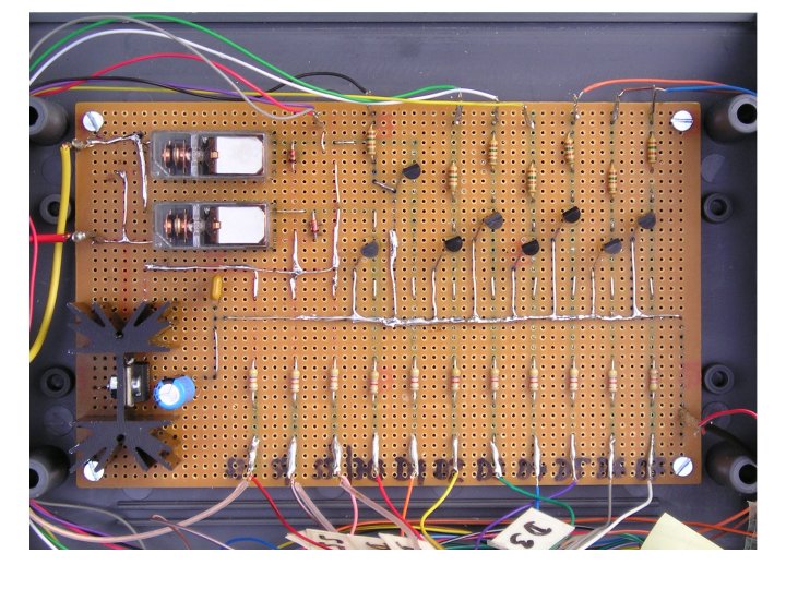
Layout
of the board in the control box, a click leads to the diagram (mouse
click effekt)
1.3
Redundancy
The horn is wired parallel with both relays (ports). With a click on
each icon both relays (ports) can be tested separately before the game
starts.
If one of the connections for the referee signalling devices does not
work, it is possible to change to another one, if all entryways S3 to
S6 are wired up. This change has to configured in the program.
2.
Software
The software does not only work as a program on the hardware described
above, but also as Java applet within a browser. The applet launches
completely from the Java archiv "SchiriAnlage.jar" except for the
images and the templates. The applet does not have access to the
hardware (Java security). Therefore the simulation modus is activated,
i.e. the thread "ParallelPort-Kommunikation" does not open the fifos.
Instead the signal from the referee is simulated by a click on the
corresponding referee icon (circle).
For the utilization as referee device you need:
- Linux (tested with Suse 8.1) as operating system,
- a Java Runtime Environment JRE (e.g.
from Suse 8.1 or higher),
- the C-program "ParallelPortControl" or the source file
"ParallelPortControl.c",
- all class files (SchiriAnlage.class, Schiedsrichter.class,
SchiedsrichterLicht.class, ...) or the source file
"SchiriAnlage.java"
from the Java program,
- the template for the protocol "protokollTemplate.html",
- possibly a language file "language.html",
- if necessary a prepared team config
file "mannschaftsconfig.html" (see:
full protocol),
- all icons in the directory "images" and
- the Shell script "runSchiriAnlage.sh".
2.1 Hardware
Control
The program ParallelPortControl is a very simple, slim program
for
the hardware control. It runs under root (using s-bits) and substitutes
for a driver usually doing this job (that saves me to grapple with
driver programming).
2.2 Java
Program
As always I started with the illusion that such a small GUI (Graphic
User Interface) with a little control of the program
"ParallelPortControl" could easily be implemented. Meanwhile
there
are nearly 8000 lines of code in version 2.1.
For the control of the program ParallelPortControl (see 2.1) there
exists a separate Java thread (mini process)
"ParallelPortKommunikation". All data from and to the control box are
going through this thread. If no connection can be achieved to the
program "ParallelPortControl" via the fifos (see 2.3 Fifos),
this
program change to the simulation mode and simulates the communication
(setStatusOverwrite). For the main thread there is no difference
between the simulation mode and the real operation. The simulation mode
becomes active when starting as applet or the when the fifos are not
available. In order to test the functions of the program relying on the
referee signals, there is additionally to the above the referee input
simulation (see configuration). A click on a referee icon (circle)
imitates the pressing of the corresponding referee signalling device.
The recognition of the signals (short-short-short for foul, long-long
for goal and one long continuous sound for the start or restart of the
game) works quite reliably. Nevertheless it is possible to adjust the
threshold between short and long signals (configuration). The default
value is 300 milliseconds. The only known problems arise from referee
signalling devices with unclear signal, i.e. the contact is not stable
when pressing the button.
For more information about the use of the referee device see below.
2.3 Fifos
The fifos "fifo_pp_command" and "fifo_ppc_answer" are created from the
script "runSchiriAnlage.sh" and are deleted after finishing the
program. The first one is used by the Java program to send the data for
the horn and the penalty time devices. The answer with the input from
the referee arrives within the second fifo. This occurs every 20
milliseconds.
2.3 Start
Script
The start script "runSchiriAnlage.sh" checks the essential files. If
existing, newer source files are compiled (on the condition that the
appropriate compiler is available). Then the fifos (named pipes) are
created and the programs are started. The first time and in case of
newer source files "runSchiriAnlage.sh" should be started from the
shell to see the comments and to provide the root password if needed.
Later the "runSchiriAnlage.sh" can be activated by Autostart or an icon
on the desktop, i.e. usually launch and off we go...
2.4
Why Linux, C and Java?
Because Linux is the better operating system ;-)
Seriously; Linux provides the following not available within
Windows:
- a free C compiler,
- a file system with fifos for simple and high
performing process communication,
- easy of hardware access
The programming language C for the hardware access is obvious
on a
Linux system, isn't it. There is no other reasonable way to implement
it.
The GUI is written in Java because:
- a free Java compiler exists,
- the program can be made available as applet
in the Internet,
- Java is object oriented, definitively advantageous
for this job,
- the AWT (Advanced Windowing Toolkit) makes
it possible to easily design the Graphic User Interface (newer
Swing classes are not used) and
- the threads offer a beneficial possibility to implement the
several, independently running flows of work.
2.5
Knoppix with the Referee Device Software
A lot of Windows users allready have tested Linux with a "KNOPPIX-CD"
(see e.g. the journal c't 4/2004): put in the CD, switch on the
computer and wait a little. Then a complete Linux can be seen without
installation; i.e. there are no changes to the Windows installation at
all.
Because Knoppix can be used that easily, I have
created a
modified KNOPPIX-CD.
The Referee Devices software is included and will be lauched
automatically. At the UWR tournament - where everything might be upside
down
- just wire up, switch on and wait until the software is ready.
Furthermore this prevents that by mistake the referee device software
has been changed or deleted and is not working properly. According to
requirements you can see it as a backup, too.
If you want to experience this KNOPPIX-CD you should contact
me.
3.
Usage of the Referee Device
On the 3rd of April.2004 the UWR
Referee Device was in operation
at the tournament of the SV Paderborn (2nd German league). The
concept has proven to be successful.
3.1
Prerequisites
- The hardware is put together properly.
- Linux as operating system (tested with Suse Linux
8.1, Open Suse Linux 10.0 and Knoppix 3.4; all
other distributions are presumable ok, too),
- X-Windows graphical desktop environment (e.g. KDE)
and
- Java 1.3 or higher (Runtime Environment, or better JDK) is
installed.
- The software is located on a Linux file system because of
the fifos (do not use FAT, NTFS, ...).
3.2
Let's get started ...
After all parts are connected and the software is on the system, you
start the script "runSchiriAnlage.sh" with a regular user account.
Doing this the first time or after an update it is better to use a
shell.
When all tests and compilations have been finished
successfully (If the program "ParallelPortControl" has to be
compiled or does not have the correct rights, you are prompted to give
the root password.), the Java program will appear on
the
screen.
With a click on a horn icon you can test each of the horns
relays
separately, as long as the game is not activated. The referee
signalling devices can be tested with the "Signal Test".
Before the game starts you should check the parameter via the
configuration button. Most entries should be self explanatory. The
"short/long signal threshold" defines the bound for the signal to be consider
as long. With With
Mit
"full protocol +
autom. goal display"you
make a key decision. With the default "no" only minimal input is
needed (Penalty throw, time penalty, time out, ...). The
complete information, e.g. who
made the goals, is obviously not known by the program with
this setting. But if you choose "yes", all
the data will be requested to produce a complete protocol. Of course
you have to enter all teams before the game starts or open an saved
team configuration from the last game. If you want to print this
protocol, you need in
addition a printer that reasonably is not connected with the parallel
port but via USB or network.
You go on with the Activate button. The referees will take over the control with their signals. If a Penalty-time is
decided, the penalty time for the player has to be started. Accordingly for Penalty-throw, etc. When the first
half or the time of the Penalty-throw has run down, the program will honk automatically (long-long-long-long-long). After first
half
the break time will be started and thenceforth the second half will
activated.
Using the icons Goal and Foul the automatic recognition of the program
can be corrected as long as the game is not resumed by referee. The protocol button provides all the information of
the runnig game.
The time for the penalty throw and the penalty time will start running
with the referee signal. Exception: The resume signal has been given
allready. The control desk can start the time "quasi delayed" with the
button.
4.
Download, Licenses ...
The software may be used by other clubs for free. I suppose I will apply the GPL in future. But for now:
- Any club may construct their own hardware (little foto for my collection) and will get the software for free: Zip file for download.
- The hardware shall be sold. Then I want to have a share of the price.
5.
Disclaimers
Though I have tested the software and hardware with my own computer
(and I'm very particular about it), I assume no liability for
possibly occuring damage. In any case you should be careful while
playing about the parallel interface. High voltage or high current
might have destroyed some interface.
6.
Links


